Honing vs. Skiving-Roller Burnishing: Internal Surface Finishing for Hydraulic Cylinder Tubes
The internal surface finish of precision steel tubes for hydraulic cylinders directly impacts seal life, friction characteristics, and system efficiency. Two dominant finishing methods—honing and skiving-roller burnishing (SRB)—produce different surface topographies with distinct performance implications. Understanding these differences enables optimal specification for specific operating conditions.
Honing creates a cross-hatched pattern through abrasive stone contact, removing material to achieve surface roughness values of Ra 0.2-0.4 μm. The controlled plateau structure provides oil retention pockets that enhance lubrication during piston seal movement. Typical honing angles range from 45-65 degrees, with 50-55 degrees optimal for most hydraulic applications. Material removal rates vary from 0.05-0.15mm per pass, requiring precise control to maintain tight diameter tolerances.
Skiving-roller burnishing combines material removal (skiving) with plastic deformation (burnishing) in a single operation. This process achieves superior surface finishes of Ra 0.05-0.2 μm while simultaneously improving dimensional accuracy and surface hardness. The burnishing action increases surface microhardness by 15-30% through work hardening, extending wear resistance. Our integrated manufacturing capabilities allow us to select the optimal finishing method based on your specific cylinder bore diameter, stroke length, and operating pressure requirements.
| Process Characteristic |
Honing |
Skiving-Roller Burnishing |
| Surface Roughness (Ra) |
0.2-0.4 μm |
0.05-0.2 μm |
| Diameter Tolerance Achievable |
H8 ±0.014−0.027mm |
H7 ±0.010−0.018mm |
| Surface Hardness Increase |
None |
15-30% increase |
| Production Speed |
0.3-0.8 m/min |
0.8-2.5 m/min |
| Best Application |
Heavy-duty, low-speed cylinders |
High-speed, precision positioning |
For construction machinery operating in contaminated environments, the deeper valleys created by honing provide better dirt particle accommodation, reducing abrasive wear on seals. Conversely, precision steel tubes for hydraulic cylinders in clean industrial environments benefit from the ultra-smooth SRB finish, which minimizes friction and extends seal service intervals by 40-60%.
Material Hardness Requirements Across Different Operating Pressure Ranges
Hydraulic cylinder tube material hardness must be matched to system operating pressure to prevent permanent deformation, resist wear, and maintain dimensional stability throughout service life. Insufficient hardness allows gradual bore enlargement from seal friction and pressure-induced yielding, while excessive hardness may reduce toughness and increase susceptibility to stress corrosion cracking.
For low-pressure hydraulic systems (below 100 bar), typical in mobile equipment auxiliary functions, cold-drawn seamless tubes with minimum hardness of 140-170 HB provide adequate performance. These softer materials offer excellent machinability for port drilling and threading operations while maintaining sufficient wear resistance for seal compatibility.
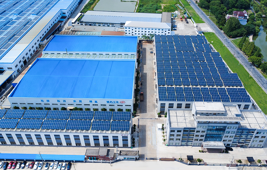
Medium-pressure applications (100-250 bar), common in construction machinery and industrial presses, require hardness levels of 180-220 HB. At our facilities spanning 36,000 square meters, we employ controlled heat treatment processes to achieve consistent hardness profiles throughout the tube wall thickness, ensuring uniform performance under cyclic pressure loading.
High-pressure hydraulic cylinder tubes operating above 250 bar demand minimum hardness of 220-280 HB. For ultra-high-pressure systems exceeding 400 bar in injection molding machinery and heavy presses, hardness values of 280-320 HB are specified. These applications typically utilize quenched and tempered alloy steels such as ASTM A519 4140 or DIN 2391 St52, which combine high strength with acceptable ductility.
- Surface hardness vs. core hardness: Through-hardened tubes provide uniform properties but may exhibit reduced toughness. Induction-hardened tubes offer hard wear-resistant surfaces (55-62 HRC, equivalent to 650-850 HB) with tough cores (180-220 HB), ideal for abrasive environments
- Hardness testing locations: Specifications should define measurement positions—typically mid-wall thickness at multiple locations along tube length to verify heat treatment uniformity
- Hardness gradient limits: Excessive hardness variation (>30 HB difference) between surface and core indicates improper heat treatment, potentially causing residual stress issues
Calculating Wall Thickness for Pressure Vessel Compliance in Hydraulic Applications
Precision steel tubes for hydraulic cylinders function as pressure vessels and must be designed according to relevant standards such as ISO 3320, ASME B31.3, or national pressure equipment directives. Wall thickness calculation involves multiple factors beyond simple hoop stress, including manufacturing tolerances, corrosion allowances, and safety factors specific to hydraulic service.
The fundamental wall thickness equation for thin-walled cylinders (D/t > 20) under internal pressure is: t = (P × D) / (2 × S × E × W), where P = design pressure, D = outside diameter, S = allowable stress, E = weld joint efficiency (1.0 for seamless tubes), and W = weld strength reduction factor (1.0 for seamless). This basic calculation must then be modified for practical application.
Manufacturing tolerance adjustments account for wall thickness variations inherent in cold-drawing processes. For seamless precision steel tubes, thickness tolerance is typically ±10-12.5% of nominal wall. Conservative design practice subtracts the negative tolerance from calculated thickness, ensuring minimum wall meets pressure requirements even at tolerance extremes. Our online dimensional monitoring systems track wall thickness variations continuously, providing statistical process control data that enables tighter tolerance bands (±8%) for critical applications.
Additional Wall Thickness Considerations
- Corrosion allowance: Hydraulic cylinder tubes exposed to corrosive environments require 1-3mm additional thickness depending on service life expectations and fluid compatibility. Water-glycol fluids are more corrosive than petroleum oils, necessitating higher allowances
- Threading allowance: Cylinder tubes with threaded ports or end connections require sufficient wall thickness to accommodate thread depth plus minimum remaining wall for pressure containment. NPT threads remove approximately 0.8 times the thread pitch in material depth
- Fatigue considerations: Cyclic pressure loading reduces allowable stress to 30-50% of static values depending on cycle count and stress amplitude. Hydraulic cylinders exceeding 100,000 cycles require fatigue analysis per standards like DIN 3320 or ISO 3320
- Buckling resistance: Long, thin-walled hydraulic cylinder tubes may buckle under compressive loading before reaching pressure-induced stress limits. Buckling calculations consider tube length, end fixity, and external loads
For thick-walled cylinders (D/t < 20), common in high-pressure applications, Lame's equation provides more accurate stress distribution accounting for radial stress variation through the wall thickness. Maximum stress occurs at the inner surface: σ_tangential = P ×(Do²+Di²)/(Do²−Di²), where D_o and D_i are outer and inner diameters respectively.
Straightness Specifications and Their Impact on Cylinder Assembly and Performance
Hydraulic cylinder tube straightness directly affects assembly efficiency, seal alignment, piston rod bearing loads, and overall cylinder performance. Excessive bow or waviness causes uneven seal contact pressure, accelerated wear patterns, increased friction, and potential rod bending under side loads. Specifying appropriate straightness tolerances requires understanding the relationship between tube geometry and cylinder function.
Industry standards typically express straightness as maximum deviation per unit length (mm/m) or total indicator reading (TIR) over total tube length. Common specifications range from 0.5 mm/m for general industrial cylinders to 0.15 mm/m for precision positioning systems. With advanced multi-roll straightening equipment across our two production facilities, we routinely achieve straightness values of 0.2 mm/m, enabling trouble-free assembly and extended service life.
The relationship between straightness and seal performance becomes critical in long-stroke cylinders. A 3-meter hydraulic cylinder tube with 1.5mm total bow 0.5mm/m creates varying radial clearances as the piston traverses the bore. At the apex of the bow, seal compression may be insufficient for effective sealing, while at other positions, excessive compression increases friction and heat generation. Maintaining straightness below 0.3 mm/m ensures seal contact pressure variation remains within acceptable limits (±15% of nominal).
Measurement and Verification Methods
- V-block method: Tube supported on precision V-blocks at specified intervals (typically L/3) with dial indicator measuring deviation at mid-span. Suitable for tubes up to 6 meters with accuracy ±0.02mm
- Rotary straightness measurement: Tube rotated while supported on centers with laser or dial indicator scanning full circumference. Detects both bow and ovality simultaneously, providing comprehensive geometry data
- Coordinate measuring machine (CMM): For critical applications requiring straightness verification better than 0.1 mm/m, CMM systems provide three-dimensional measurement with ±0.005mm accuracy
Residual stress from cold drawing can cause delayed straightness deviation after initial measurement. Stress-relief annealing at 500-600°C stabilizes tube geometry by relieving internal stresses that might otherwise cause gradual bowing during service or machining. For precision steel tubes for hydraulic cylinders in critical applications, we recommend stress-relief treatment followed by final straightening to achieve permanent geometric stability.
Seal Groove Geometry Optimization for Different Seal Types in Hydraulic Cylinders
While many hydraulic cylinder designs incorporate seal grooves in pistons or glands rather than the tube itself, certain configurations—particularly composite seals and specific rod wiper installations—require precise groove dimensions machined into the hydraulic cylinder tube bore. Groove geometry significantly impacts seal function, installation ease, and service life.
O-ring seals in static applications require groove depths of 70-85% of O-ring cross-section diameter to achieve proper squeeze. For a 3mm cross-section O-ring, groove depth should be 2.1-2.55mm with width 1.4-1.6 times the cross-section 4.2−4.8mm. Insufficient depth reduces squeeze below the minimum 10-15% required for effective sealing, while excessive depth allows extrusion under pressure.
U-cup and V-packing seals designed for dynamic sealing in pistons may occasionally be mounted in cylinder bore grooves for specialized applications. These configurations require asymmetric groove profiles accommodating seal lip geometry. Groove depth typically equals 60-75% of seal axial height, with lead-in chamfers of 15-20 degrees facilitating installation without lip damage. Surface finish within grooves should not exceed Ra 1.6 μm to prevent seal lip cutting during operation.
| Seal Type |
Typical Groove Depth |
Groove Width Tolerance |
Corner Radius |
| O-ring (Static) |
70-85% of cross-section |
+0.1/+0.3mm |
0.2-0.4mm |
| U-cup (Dynamic bore mount) |
60-75% of seal height |
+0.0/+0.2mm |
0.3-0.5mm |
| Wiper seal (Bore mounted) |
85-95% of seal height |
+0.0/+0.15mm |
0.2-0.3mm |
| Composite seal (Bore mounted) |
Per manufacturer spec |
±0.05mm |
0.1-0.2mm |
Critical groove dimensions include corner radii, which must be large enough to prevent stress concentration and seal damage, yet small enough to prevent seal extrusion into corners under pressure. Sharp corners (radius < 0.1mm) cut elastomeric seals, while excessive radii reduce effective groove volume and seal retention. Manufacturing groove features in hardened hydraulic cylinder tubes requires specialized tooling and precise depth control to maintain dimensional accuracy.
Thermal Expansion Compensation in Long-Stroke Hydraulic Cylinder Design
Temperature variations during hydraulic cylinder operation cause dimensional changes in both the tube and piston assembly. For short-stroke cylinders (< 500mm), thermal expansion effects are negligible, but long-stroke applications in construction machinery, marine systems, and industrial presses require explicit consideration to prevent binding, seal damage, or loss of positional accuracy.
Carbon and low-alloy steels commonly used for hydraulic cylinder tubes exhibit linear thermal expansion coefficients of approximately 11-13 × 10⁻⁶ per °C. A 3-meter hydraulic cylinder tube experiencing a 40°C temperature rise (ambient to operating temperature) expands approximately 1.44mm in length. If the cylinder mounting configuration constrains this expansion, compressive stresses develop that may cause buckling in thin-walled designs or exceed material yield strength.
Radial expansion affects bore diameter and seal clearances. The same 40°C temperature increase on a 100mm bore diameter causes approximately 0.048mm diameter growth. While this seems minor, it represents a 0.024mm change in radial clearance per side—potentially significant for precision positioning systems or high-pressure seals operating near minimum clearance limits. As a manufacturer with comprehensive testing capabilities across our 50,000+ ton annual production volume, we can provide thermal expansion data for specific material grades and operating temperature ranges.
Design Strategies for Thermal Management
- Floating mount configuration: One cylinder mounting point (typically rod end) uses slotted holes or sliding plates allowing longitudinal movement. This prevents thermal stress buildup while maintaining alignment
- Material matching: Using similar materials for tube, piston, and rod minimizes differential expansion. Aluminum pistons in steel cylinders require special clearance considerations due to aluminum's higher expansion coefficient (23 × 10⁻⁶ per °C)
- Clearance adjustment: Seal clearances specified at operating temperature rather than ambient, with installation clearances adjusted accordingly. Cold-temperature starting may require temporary bypass or reduced pressure until thermal expansion closes clearances
- Temperature stabilization: Systems with critical positioning requirements incorporate thermal insulation or active temperature control maintaining cylinder within ±5°C variation, limiting expansion effects to acceptable levels
Extreme temperature applications—such as steelmaking equipment operating at 200°C or arctic mobile machinery functioning at -40°C—require specialized material selection and design analysis. High-temperature service may necessitate alloy steels with enhanced creep resistance, while cold-temperature operation demands materials maintaining adequate toughness (Charpy V-notch > 27J) at minimum operating temperature to prevent brittle fracture.
Port Connection Thread Types and Torque Requirements for Hydraulic Cylinder Tubes
Threaded port connections in precision steel tubes for hydraulic cylinders must withstand full system pressure while allowing assembly/disassembly for maintenance. Thread form selection impacts sealing reliability, assembly torque, and tube wall stress distribution. Common hydraulic thread types include NPT (National Pipe Taper), BSPT (British Standard Pipe Taper), metric parallel with O-ring (ISO 6149), and straight thread O-ring boss (SAE J1926).
NPT and BSPT threads create metal-to-metal seals through interference between tapered male and female threads. Thread taper is 1:16 for both standards, with NPT using 60-degree thread angle and BSPT using 55 degrees. These threads require thread sealant (PTFE tape or pipe dope) and develop sealing through deformation when tightened. Torque specifications range from 20-60 N⋅m for 1/4" connections to 200-500 N⋅m for 1" connections depending on pressure rating and material.
Straight thread O-ring connections (ISO 6149, SAE J1926) provide superior sealing reliability and allow precise torque control without affecting seal compression. The O-ring, compressed in a chamfered seat, creates the hydraulic seal while threads provide mechanical retention only. This separation of sealing and clamping functions eliminates the variability inherent in tapered thread seals. Recommended torque values are precisely specified: for example, M14×1.5 ISO 6149 requires 30±3 N⋅m regardless of pressure, as overtightening damages the O-ring without improving seal performance.
| Thread Type |
Sealing Method |
Typical Pressure Rating |
Reusability |
| NPT/BSPT (Tapered pipe) |
Metal-to-metal + sealant |
Up to 400 bar |
Limited (3-5 cycles) |
| ISO 6149 (Metric straight + O-ring) |
O-ring in chamfer |
Up to 630 bar |
Excellent (50+ cycles) |
| SAE J1926 (Straight thread O-ring boss) |
O-ring on flat face |
Up to 420 bar |
Excellent (50+ cycles) |
| JIC 37° flare |
Metal-to-metal cone |
Up to 600 bar |
Good (20-30 cycles) |
Minimum wall thickness remaining after thread machining critically affects pressure containment capability. Industry practice requires minimum remaining wall of at least 3mm for pressures up to 250 bar, increasing to 5-8mm for pressures exceeding 400 bar. Thread engagement length should be at least 1.5 times the nominal thread diameter for full strength development. Our engineering team can assist in port location planning to ensure adequate wall thickness while accommodating required connections.